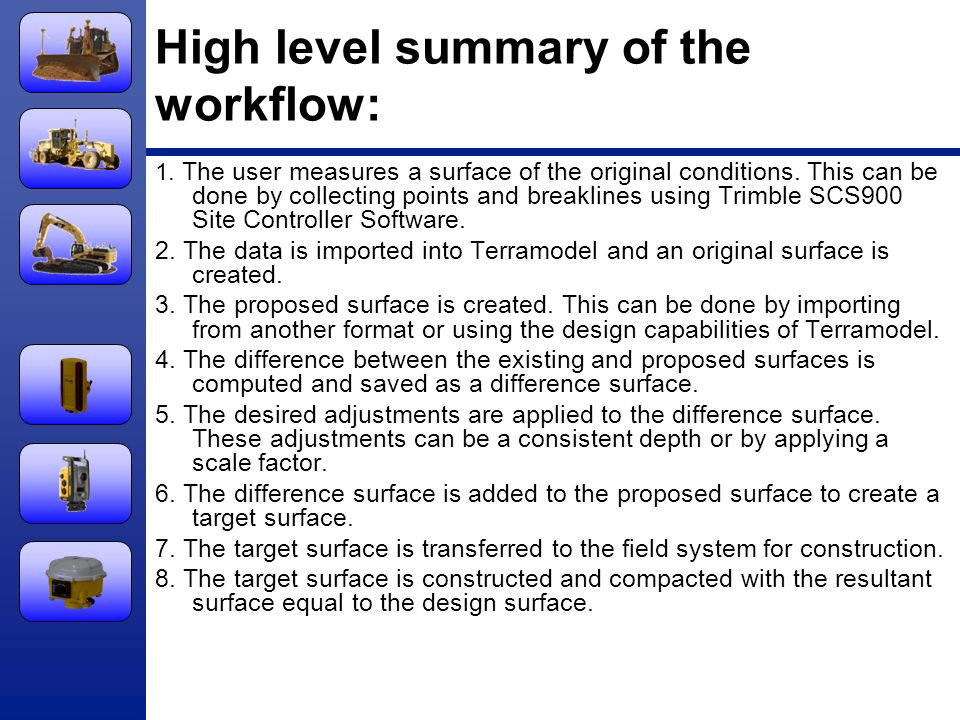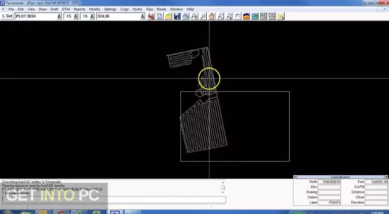

Hover your mouse cursor over a point in the Plan window and note the information tooltip window that appears after a moment (see figure above). Fortunately, the survey data for this file was imported so that features are named by the survey point code (see exercise Importing ASCII Survey Data). It would also be nice to see other surveyed features like pavement edges and the road center line. As shown in the previous exercise, breaklines are required to define the surface realistically. Notice that the road is not well defined. Note: Refer to Getting Started section for file install folders ( and ).įile | Open \DTM\ Topo no breaklines.terx.įigure 1: 3D and Plan Windows, File: Topo no breaklines.terx. Join points to create a polyline feature.įormat feature colors, symbols and line styles. To perform this task, you will learn about the following Terrain functions: In this exercise, you will add some breaklines to a data set that consists of nothing but points. Sometimes, however, it is easier to simply connect the dots.


The files referenced in the article, as well as the full tutorial document, are available in our Tutorial Installer.Īs seen in Importing ASCII Survey Data, breaklines can be created automatically. This Knowledge Base article is an excerpt from one of our tutorial files.


 0 kommentar(er)
